
Guide 23: Design for Manufacturability (DFM): 10 Simple Changes That Can Cut CNC Machining Costs
Small CAD changes can lead to massive manufacturing savings. Discover 10 practical DFM strategies—from relaxing unnecessary tolerances to optimizing pocket depths—that dramatically reduce CNC machining time and production costs.
Guide 23: Design for Manufacturability (DFM): 10 Simple Changes That Can Cut CNC Machining Costs
10 Simple Design Changes That Can Cut CNC Machining Costs | Manufacturing Academy
One of the biggest misconceptions in product development is that if a part can be machined, it is ready for production.
In reality, two parts with the same function can have dramatically different manufacturing costs. A few small design decisions—such as specifying an unnecessary tolerance or creating an overly deep pocket—can double machining time without adding any real value.
This is where Design for Manufacturability (DFM) makes a difference. DFM is the process of designing parts that are not only functional but also easier, faster, and more cost-effective to manufacture.
1. What Is Design for Manufacturability (DFM)?
DFM is the practice of optimizing a design for efficient manufacturing. Instead of asking: "Can this part be machined?", ask: "Can this part be machined efficiently, repeatedly, and economically?"
A well-designed part yields lower costs, shorter lead times, better consistency, fewer issues, and higher overall quality.
2. 10 Practical DFM Cost-Reduction Changes
Avoid Unnecessarily Tight Tolerances
Over-specifying tolerances is a major cost driver. Many drawings apply ±0.01 mm to every feature unnecessarily.
Feature | Recommended Tolerance |
General dimensions | ±0.10 mm |
Standard machined features | ±0.05 mm |
Precision fits | ±0.01–0.02 mm |
Increase Internal Corner Radii
End mills are round. Sharp internal corners require tiny cutting tools, slower feed rates, longer cycle times, and higher tool wear. Recommended: Internal radius ≥ tool radius. Larger radii allow larger, more rigid tools and faster machining.
Reduce Deep Pocket Depth
Deep pockets require long tools prone to vibration and deflection. Guideline: Pocket depth ≤ 4 × tool diameter. If deeper pockets are necessary, widen the pocket to fit a larger cutter.
Standardize Hole Sizes
Use standard drill and reamer sizes. Minimize the variety of hole diameters in a single part to cut down tool changes and cycle time.
Limit Extremely Thin Walls
Thin walls flex during cutting, causing chatter, poor finish, and dimensional errors.
Material | Recommended Minimum Thickness |
Aluminum | 0.8–1.0 mm |
Steel | 1.5 mm |
Plastics | 1.0–1.5 mm |
Simplify Complex Geometry
Eliminate non-functional features like decorative pockets, tiny cosmetic grooves, small fillets, or complex non-functional contours.
Minimize Setups
Every re-positioning requires re-aligning workpieces, datums, and re-inspection. Design parts so most features can be machined in 1 or 2 setups.
Choose Readily Available Materials
Standard stock materials reduce procurement lead times and cost:
· Metals: Aluminum 6061, Aluminum 7075, Stainless Steel 304, Stainless Steel 316, Mild Steel
· Plastics: Delrin (POM), Nylon, ABS, Polycarbonate, PEEK (only when required)
Design Features Around Standard Cutting Tools
Design around standard slot widths, corner radii, hole diameters, and thread sizes to avoid custom tooling fees.
Involve Your Manufacturer Early
Engage CNC suppliers before finalizing CAD files to get expert advice on machining strategies, economical tolerances, and material choices.
3. Real-World Example & DFM Checklist
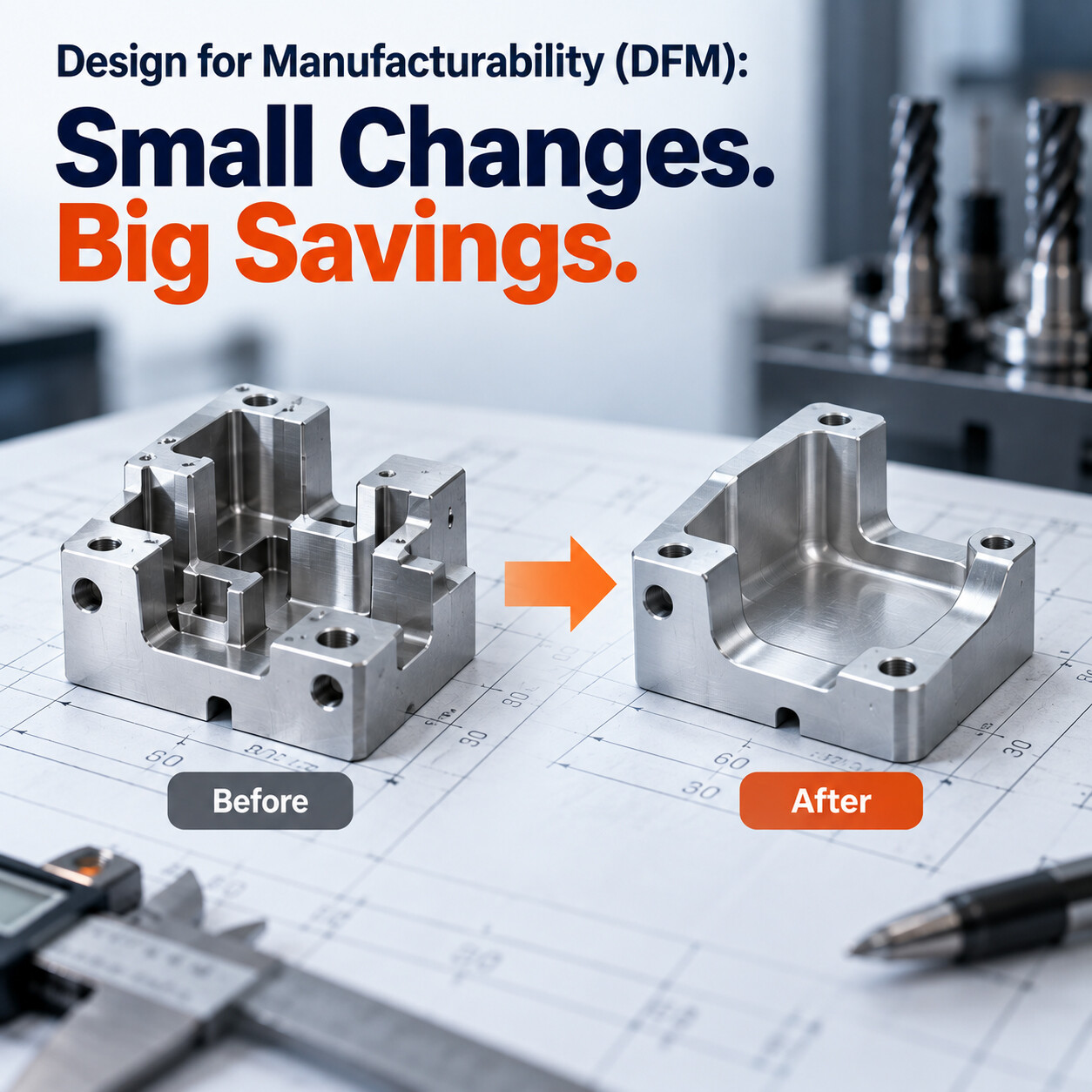
Example (Aluminum Mounting Bracket):
· Part A (Before DFM): Sharp internal corners, 6 hole sizes, deep pockets, ±0.01 mm tolerance throughout → 45 minutes machining time.
· Part B (After DFM): Larger corner radii, standardized holes, shallower pockets, functional tolerances → 25 minutes machining time (44% reduction!).
DFM Checklist before submitting CAD:
· Are all tight tolerances functionally necessary?
· Can internal radii be increased?
· Are pocket depths reasonable (≤ 4x tool diameter)?
· Are hole sizes and threads standardized?
· Are walls thick enough to prevent flexing?
· Can non-functional features be removed?
· Can machining setups be reduced?
· Is the selected material standard and readily available?
· Are standard tools sufficient?
· Has a manufacturing engineer reviewed the file?
4. Conclusion
Good engineering isn't just about creating parts that work—it's about creating parts that work efficiently. Applying DFM principles early reduces machining time, lowers costs, improves consistency, and shortens lead times.
Key Takeaways
· DFM focuses on designing parts that are easier and more economical to manufacture.
· Relax unnecessary tolerances to reduce machining and inspection costs.
· Use larger corner radii, standard hole sizes, and reasonable pocket depths.
· Design around standard cutting tools and minimize multiple setups.
· A professional DFM review before production can prevent costly redesigns and improve manufacturing efficiency.
Want this reviewed on your own part?
Upload your CAD file for a free DFM review. Our engineering team will assess manufacturability, material and process options, and cost drivers for your design.
Get a Free DFM Review