
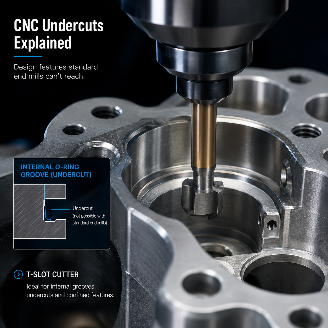
Guide 15: CNC Undercuts Explained: How to Design Features Standard End Mills Can't Reach
This DFM guide explains CNC undercuts—features that standard vertical end mills cannot reach—and outlines specialized cutting tools such as T-slot, dovetail, and lollipop cutters. It details functional applications like O-ring seals and retaining ring channels, while providing essential design rules to optimize manufacturability and control manufacturing costs.
Guide 15: CNC Undercuts Explained: How to Design Features Standard End Mills Can't Reach
Undercut Tools, Design Rules & DFM Guidelines | Manufacturing Academy
1. Introduction
The vast majority of CNC machined features—such as standard pockets, open slots, bosses, and holes—are designed for direct line-of-sight access along the machine spindle axis. Standard end mills reach these areas straightforwardly from above.
However, high-performance mechanical designs frequently require recessed internal grooves, captive retaining rings, O-ring seal seats, or interlocking slide rails that are physically blocked by overhangs from a vertical tool path. These hard-to-reach geometric features are known as undercuts. While undercuts enable key functionality in aerospace, medical, and automotive assemblies, they demand specialized cutting tools, custom CAM strategies, and careful DFM planning to avoid unnecessary manufacturing expenses.
2. What Is an Undercut?
In CNC machining, an undercut is defined as any feature geometry that cannot be accessed or swept by a standard vertical end mill moving parallel to the main spindle orientation (Z-axis).
Common examples of undercut features include:
Internal O-Ring & Sealing Grooves: Recessed channels inside cylinders or valve bodies.
Retaining Ring / Snap-Ring Grooves: Internal radial slots engineered to hold circlips.
T-Slots & Keyways: Linear retaining channels used on machine tables and sliding fixtures.
Dovetail Slide Guides: Angled trapezoidal tracks providing mechanical locking alignment.
Under-Shoulder Relief Cutouts: Recesses placed behind bearing journals or ground threads.
3. Why Are Undercuts More Complex and Costly to Machine?
Because undercut surfaces are shielded by overhanging wall geometry, standard end mills cannot cut them from directly above. Machining an undercut introduces several engineering constraints:
Specialized Tool Requirements: Requires necked or shaped tooling such as T-slot cutters, dovetail mills, or spherical lollipop cutters.
Tool Rigidity & Vibration Risks: Undercut tools feature narrow tool shanks or long overhangs, making them susceptible to chatter and deflection.
Reduced Material Removal Rates (MRR): Feed rates and depth of cut must be reduced to protect delicate tools.
Extended CAM Programming & Cycle Times: Requires multi-axis entry toolpaths, clearance checks, and cautious tool retract moves.
4. Specialized Cutters for Undercut Machining
1. T-Slot Cutters (Slotting Mills)
T-slot cutters feature a thin connecting neck with a wider circular cutting disc at the tip. They move laterally into the workpiece wall to create internal horizontal grooves, T-slots, and retaining ring channels.
2. Dovetail Cutters
Dovetail cutters feature inverted conical cutting edges, typically ground to specific included angles (e.g., 45°, 60°). They machine precision angled tracks that lock mating slide components together without external fasteners.
3. Lollipop Cutters (Spherical End Mills)
Lollipop cutters have a full spherical cutting head supported by a slender shank. They excel at machining complex 3D contoured undercuts, internal fillet radii, mold cavity reliefs, and multi-axis aerospace components.
5. Functional Applications for Undercuts
Undercuts should be specified when they provide irreplaceable mechanical advantages:
Fluid & Gas Tight Sealing: O-ring grooves inside hydraulic blocks demand undercut profiles to prevent seal displacement under high pressure.
Fastenerless Mechanical Interlocking: Snap-fits, bayonet mounts, and dovetails eliminate the weight and hardware cost of external bolts.
Precision Bearing Seat Reliefs: Relief grooves behind shaft shoulders allow mating bearings or bushings to sit flush against reference faces.
6. Tooling Comparison for Undercut Machining
Cutter Type | Primary Application | Key Advantages | Main Limitations
|
T-Slot Cutter | Linear T-slots, internal circlip grooves, side slots | High horizontal cutting efficiency, precise groove width | Limited vertical plunge depth, requires side entrance clearance |
Dovetail Cutter | Trapezoidal sliding tracks, mechanical clamps | Single-pass dovetail geometry creation | Fixed angle geometry; tool corner wear can alter profiles |
Lollipop Cutter | Complex 3D internal curves, deburring back edges | Spherical cutting freedom in multi-axis setups | Slender neck limits heavy roughing cuts; higher tool cost |
7. Design Guidelines for Machinable Undercuts (DFM)
Design Around Standard Cutter Dimensions: Specify groove widths, radii, and dovetail angles that match off-the-shelf catalog tooling (e.g., standard 3mm or 6mm slot widths, 60° dovetails). Custom cutter grinding increases cost significantly.
Ensure Generous Tool Clearance: Provide sufficient open space for the cutter shank and neck to enter, traverse, and exit the undercut zone without striking adjacent pocket walls.
Minimize Undercut Depth: Keep the radial reach (groove depth) as shallow as functional requirements allow. Deeper undercuts require thinner necks, leading to severe tool chatter.
Maintain Uniform Feature Geometry: Standardize undercut widths and radii across the part to minimize tool changes and simplify programming.
8. Can 5-Axis CNC Machining Eliminate Undercuts?
In many instances, yes. A 5-axis CNC machining center can tilt the workpiece relative to the spindle, bringing hidden surfaces into direct line-of-sight for standard end mills. However, 5-axis machining carries a higher hourly machine rate. For simple grooves or linear T-slots, using a standard undercut tool on a 3-axis machine is often faster and more economical.
9. Common Undercut Design Mistakes
Cosmetic Undercuts: Incorporating decorative internal grooves that add machining cost without enhancing structural or mechanical function.
Trapped Tool Paths: Designing undercut pockets with no clearance path for tool insertion or retraction.
Excessive Undercut Depth: Requesting deep undercut profiles that exceed standard cutter neck-to-head aspect ratios.
Sharp Internal Undercut Corners: Failing to include corner radii, causing localized stress concentrations and tool tip chipping.
10. Recommended Design Practices (DFM Checklist)
✔ Validate Necessity: Include undercuts only when alternative designs (such as split multi-piece assemblies) are unfeasible.
✔ Match Tooling Catalogs: Size grooves and angles to match standard off-the-shelf T-slot and dovetail cutters.
✔ Verify Approach Paths: Confirm in CAD that cutter bodies have unobstructed entry/exit clearance.
✔ Keep Depths Shallow: Minimize radial depth to preserve tool rigidity and maintain surface finish quality.
11. Conclusion
Undercuts allow engineers to design compact, high-functionality mechanisms with built-in sealing, retention, and locking features. By understanding how undercut tools operate and designing features around standard cutter sizes and clearance requirements, you can achieve sophisticated part performance while keeping manufacturing costs under control.
Need Help Evaluating Complex CNC Features?
Our engineering team performs thorough DFM analyses on complex CAD geometries before production. We identify trapped tool paths, evaluate undercut feasibility, and suggest standardized tooling solutions to reduce cycle times and lower costs.
Upload your CAD files today to receive expert DFM feedback and an instant CNC machining quotation.