
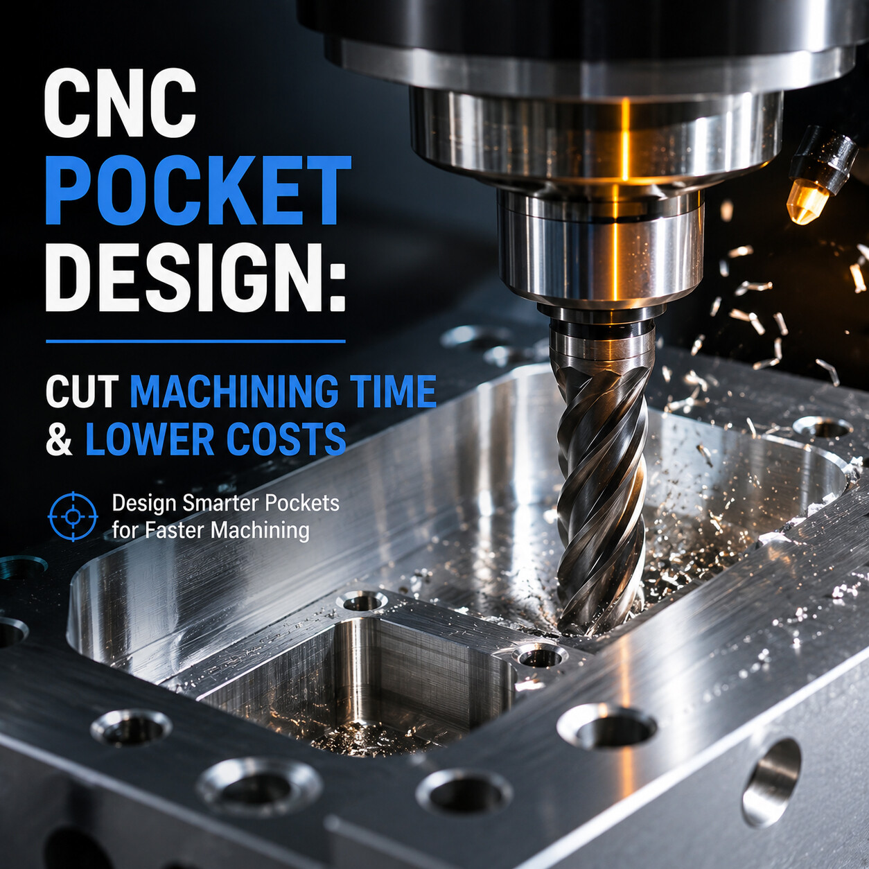
Guide 11: CNC Pocket Design Best Practices
This guide outlines DFM rules for CNC pocket design to reduce machining time and production costs. It provides practical tips on optimizing pocket depth, clearance, and internal radii while preserving part performance.
Guide 11: CNC Pocket Design Best Practices
Reduce Machining Time Without Sacrificing Performance | Manufacturing Academy
Pocket machining is one of the most time-consuming operations in CNC manufacturing. Whether you're designing housings, brackets, mounting plates, or lightweight structural components, pocket geometry has a direct impact on machining efficiency, tool life, and production cost. Many pockets look perfectly acceptable in CAD software but become expensive once they reach the machine shop. This guide explains how to design CNC pockets that are easier to machine while maintaining the performance your part requires.
Why Pocket Design Matters
Unlike simple through-holes or external profiles, pockets require large volumes of material to be removed. Poor pocket design can lead to:
Long machining cycles
Excessive tool wear
Tool deflection and chatter
Poor surface finish
Increased vibration
Higher production costs
Good pocket design allows manufacturers to use larger, more rigid cutting tools and efficient toolpaths, resulting in shorter cycle times and improved part quality.
Key Guidelines for Manufacturable Pockets
The following table outlines standard guidelines for pocket design:
Pocket Width | Recommended Maximum Depth | Depth-to-Width Ratio Rule |
10 mm | 20 – 30 mm | 2x – 3x Depth |
20 mm | 40 – 60 mm | 2x – 3x Depth |
40 mm | 80 – 120 mm | 2x – 3x Depth |
Rule of Thumb: Keep pocket depth below 3–4 times the cutter diameter whenever possible.
Roughing vs. Finishing Operations
Efficient pocket machining typically consists of two distinct stages:
Phase | Primary Objective | Strategy |
Roughing | Remove bulk material rapidly | Prioritize high Material Removal Rate (MRR) |
Finishing | Produce final dimensions/tolerances | Use light, precise cutting passes |
Common Pocket Design Mistakes
Excessive Depth: Designing pockets deeper than necessary (> 4x tool diameter).
Narrow Cavities: Restricting cutting tool size due to tight widths.
Sharp Corners: Specifying unnecessarily sharp internal vertical corners.
Thin Floors: Leaving unsupported thin floors that flex and chatter.
Real-World DFM Optimization Example
Design Parameter | Original CAD Design | Optimized DFM Design |
Pocket Depth | 45 mm | 30 mm |
Pocket Width | 12 mm | 18 mm |
Internal Corner Radius | R1.0 mm | R3.0 mm |
Bottom Floor Thickness | 1.5 mm | 3.0 mm |
Conclusion & Key Takeaways
Depth Control: Deep pockets decrease tool rigidity and dramatically increase machining cycle time.
Width Clearance: Wider cavities enable larger end mills and faster material removal.
Radii Optimization: Generous internal radii reduce tool wear, chatter, and overall production costs.
Accessibility First: Ensure standard tools can reach every feature without specialized setups.