
Guide 12: CNC Wall Thickness Guidelines
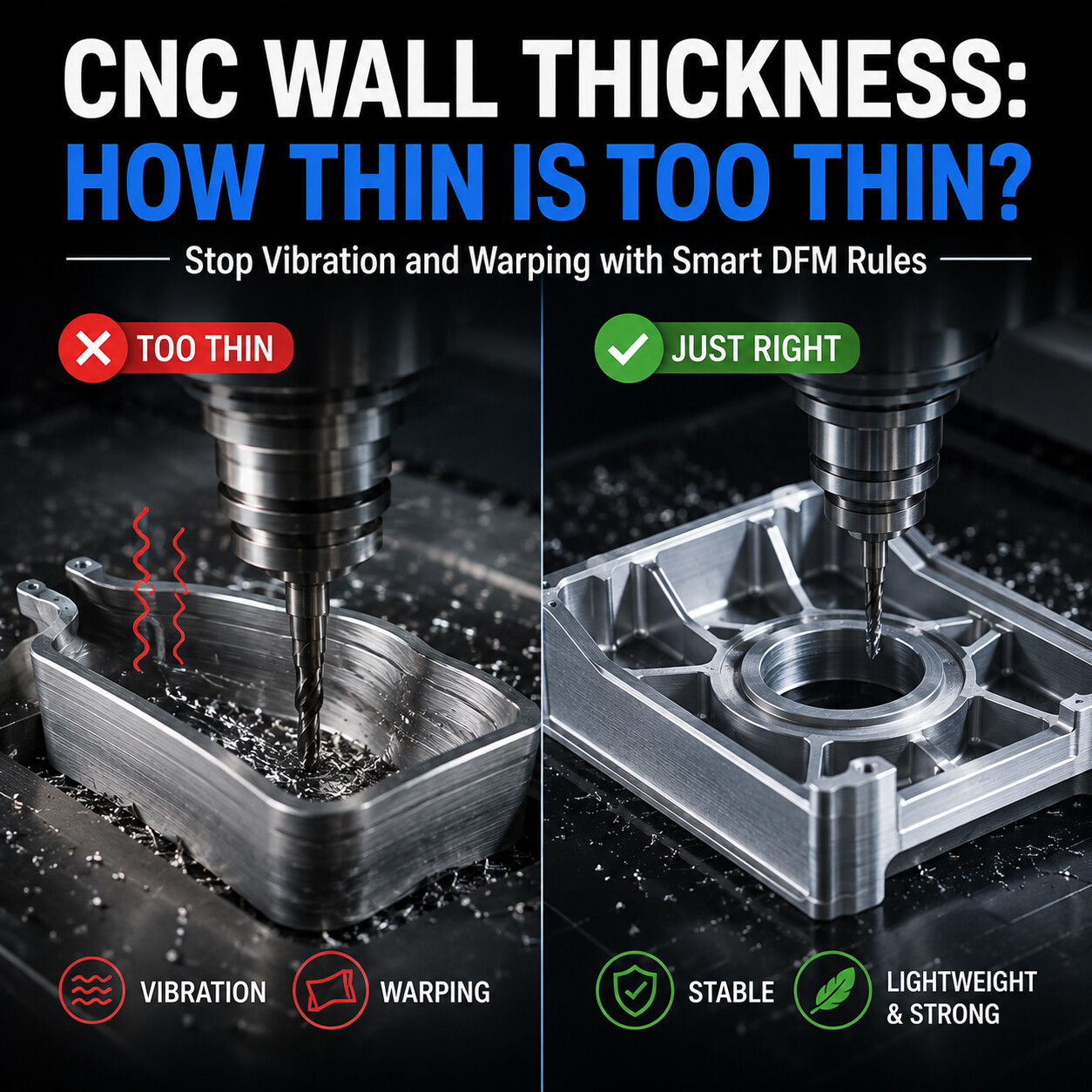
Designing thin walls can significantly lower part weight, but overly thin features often lead to tool chatter, part deflection, and thermal distortion during CNC machining. This DFM guide outlines recommended minimum wall thickness guidelines for aluminum, steel, and engineering plastics, while sharing smart design alternatives like reinforcing ribs to preserve structural integrity.
Guide 12: CNC Wall Thickness Guidelines
How Thin Is Too Thin? | Manufacturing Academy
Reducing wall thickness is one of the most effective ways to lower part weight and material consumption. However, making walls too thin creates significant manufacturing challenges. During CNC machining, thin walls are prone to vibration, deflection under cutting forces, and deformation after material stress release. Understanding practical wall thickness limits is essential for aerospace components, electronics enclosures, and mechanical assemblies.
Why Wall Thickness Matters
Wall thickness dictates nearly every aspect of the machining process:
Part Rigidity: Flexible walls deflect away from cutting tools.
Cutting Stability: Thin sections promote chatter and harmonic vibration.
Dimensional Accuracy: Hard to hold tight tolerances across flexible surfaces.
Surface Finish: Vibration leaves visible chatter marks.
Recommended Minimum Wall Thickness by Material
Material Group | Recommended Minimum Wall Thickness | Machining Behavior |
Aluminum (6061 / 7075) | 0.8 – 1.0 mm | Soft, high machinability |
Carbon Steel (1018 / A36) | 1.0 – 1.5 mm | Higher stiffness, higher forces |
Stainless Steel (304 / 316) | 1.0 – 1.5 mm | Work-hardens quickly |
Engineering Plastics (POM / ABS / PEEK) | 1.5 – 2.0 mm | Flexible, prone to warping |
The Height-to-Thickness Aspect Ratio
Wall height is as critical as wall thickness. A tall, thin wall acts like a flexible cantilever beam.
Golden Rule: Keep wall height below 10x the wall thickness (Height ≤ 10 × Thickness).
Example: A 2 mm wall performs exceptionally up to 20 mm height.
Advanced DFM Strategies
Add Reinforcing Ribs: Ribs increase mechanical stiffness dramatically with negligible weight impact.
Use Larger Corner Radii: Smooth transitions distribute mechanical stresses evenly.
Maintain Uniform Thickness: Prevents localized internal stress concentration.
Real-World Case Study: Aluminum Electronics Housing
Design Parameter | Original CAD Design | Optimized DFM Design |
Wall Thickness | 0.8 mm | 1.5 mm |
Wall Height | 80 mm (High aspect ratio) | 80 mm (with added ribs) |
Outcome | Chatter & Scrap | Perfect Stability |
Conclusion & Key Takeaways
Weight vs. Cost: Thin walls cut part weight but exponentially increase machining complexity and cost.
Material Matching: Match minimum wall thickness to material properties (Aluminum: ≥ 0.8–1.0 mm, Plastics: ≥ 1.5–2.0 mm).
Aspect Ratio: Keep the height-to-thickness ratio under 10:1 whenever possible.
Strategic Design: Use stiffening ribs instead of over-thinning walls.
Want this reviewed on your own part?
Upload your CAD file for a free DFM review. Our engineering team will assess manufacturability, material and process options, and cost drivers for your design.
Get a Free DFM Review