
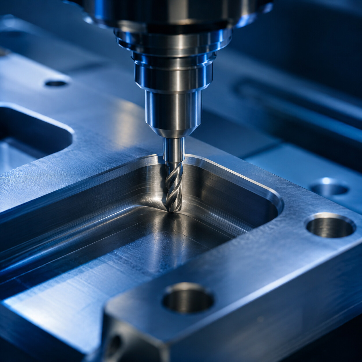
Guide 13: CNC Fillets and Chamfers: When to Use Each Feature
Fillets and chamfers play vastly different roles in CNC machining, directly impacting tool selection, cycle time, stress distribution, and overall production cost. This comprehensive DFM guide explores when to specify rounded fillets for dynamic strength and fluid flow, versus when to use beveled chamfers for fast deburring, assembly alignment, and cost-effective manufacturing.
Guide 13: CNC Fillets and Chamfers: When to Use Each Feature
Fillet vs. Chamfer, Cost Impact & DFM Guidelines | Manufacturing Academy
1. Introduction
When designing CNC machined parts, engineers often spend considerable time perfecting critical dimensions, tight tolerances, and alloy selection—while overlooking a deceptively simple detail: edge treatment. Should an edge be rounded with a radius (fillet) or beveled at an angle (chamfer)?
Although fillets and chamfers may look like minor aesthetic choices in a standard 3D CAD model, they play vastly different roles in physical manufacturing. Selecting the correct edge feature directly impacts tool selection, cycle time, stress concentration, assembly efficiency, and overall part cost. This guide provides a comprehensive DFM (Design for Manufacturability) analysis of when to specify fillets, when chamfers are the superior choice, and how to optimize edge features for cost-effective CNC production.
2. What Is a Fillet?
A fillet is a rounded transition created between two intersecting surfaces, replacing a sharp interior or exterior corner with a defined smooth radius.
In mechanical design, fillets serve several key engineering functions:
Reducing Stress Concentration: Sharp internal corners act as severe stress risers. Adding a radius distributes mechanical loads across a larger surface area.
Improving Fatigue Life: Under cyclic loading or structural vibration, fillets drastically reduce crack initiation points.
Increasing Structural Rigidity: Filleted joints enhance the section modulus at critical structural junctions.
Enhancing Ergonomics & Aesthetics: Exterior fillets eliminate harsh corners for consumer-facing parts and provide a smooth, tactile feel.
Optimizing Fluid Dynamics: In manifold blocks, impellers, and hydraulic housings, filleted internal corners reduce turbulence and flow resistance.
3. What Is a Chamfer?
A chamfer is a flat, beveled transition cut between two surfaces, typically machined at a 45° angle (though custom angles such as 30° or 60° are also utilized).
Chamfers are primarily functional features implemented across manufacturing to:
Deburr and Remove Sharp Edges: Eliminates razor-sharp burrs resulting from raw machining operations, ensuring safe handling.
Facilitate Assembly Guidance: Acts as a lead-in ramp to align mating pins, shafts, bearings, and press-fit components easily.
Protect Fasteners & Threads: Adding a chamfer to the entrance of tapped or clearance holes prevents thread damage and cross-threading during assembly.
Prevent Impact Damage: Beveled corners are significantly less susceptible to nicking or denting during transport and handling than sharp 90° edges.
4. Fillet vs. Chamfer: Key Engineering Comparison
Feature Property | Fillet (Radius) | Chamfer (Bevel)
|
Geometry | Smooth, rounded transition (constant or variable radius) | Flat, angled surface (typically 45° or custom angle) |
Primary Function | Stress reduction, fatigue resistance, structural strength | Deburring, assembly alignment, edge protection |
Machining Tooling | Ball end mills, corner rounding cutters, 3D contouring | Standard chamfer mills, countersink bits, 90° spot drills |
Machining Efficiency | Slower (requires 3D toolpaths or dedicated radius tools) | Faster (single-pass linear or 2D contour machining) |
Relative Cost | Slightly higher to significantly higher | Lower (highly economical) |
Stress Distribution | Optimal (eliminates stress concentration points) | Moderate (reduces sharp edge, but retains minor angle transitions) |
Aesthetic Profile | Smooth, organic, modern, premium finish | Clean, technical, industrial appearance |
5. When Should You Use a Fillet?
Fillets are necessary whenever mechanical strength, dynamic fatigue resistance, or fluid dynamics govern part performance:
High-Stress Structural Load Zones: Internal corners on brackets, structural ribs, and engine mounts should always feature fillets to prevent stress risers under heavy loads.
Fatigue-Critical Components: Parts exposed to recurring shock, vibration, or cyclical rotation (e.g., shafts, suspension arms, aerospace brackets) require fillets to prevent fatigue failure.
Cast or Forged Part Machining: Castings and forgings naturally form internal radii. Retaining or matching these radii during CNC finishing preserves material grain structure.
Ergonomic Exterior Surfaces: Handheld equipment, medical instruments, and premium consumer hardware benefit from external radii for comfort and aesthetics.
6. When Should You Use a Chamfer?
Chamfers are the preferred choice for general edge finishing, assembly features, and cost-conscious designs:
Edge Deburring & Operator Safety: Standardizing a 0.5 mm × 45° chamfer across exterior edges makes parts safer and easier to handle.
Mating Component Alignment: Chamfering the lead edges of shafts, housings, and dowel pin holes ensures smooth alignment during automated or manual assembly.
Threaded Hole Lead-Ins: A 90° chamfer at the mouth of a tapped hole aligns the tap and protects the lead thread from distortion.
Edge Impact Protection: External chamfers prevent fragile outer corners from chipping or denting if bumped during transit.
7. Machining Efficiency & Tooling Considerations
Understanding how CNC tools machine these features is crucial for cost optimization:
Chamfer Machining: Machining a chamfer requires a standard chamfer mill running along a single 2D toolpath contour. A single tool can machine multiple chamfer sizes across the entire part in seconds.
Fillet Machining: Machining an external or 3D surface fillet often requires a ball end mill utilizing 3D step-over toolpaths. Achieving a smooth surface finish requires small step-over increments, significantly extending machine cycle times and increasing tool wear.
8. Internal Corners and Tooling Radius Selection
When designing internal vertical corners on pockets, internal fillets are mandatory because cutting tools are circular. Always size internal radii to match standard tool availability:
Make internal radii slightly larger than the cutting tool radius (e.g., specify a 3.2 mm radius for a 6 mm cutter) to allow smooth tool movement and prevent tool chatter.
Avoid requesting extremely small internal radii unless functionally necessary, as small tools require slower feed rates and are prone to breakage.
9. Recommended Design Practices (DFM Checklist)
✔ Use Fillets where mechanical loads, stress concentrations, or fluid flow demand them.
✔ Use Chamfers for deburring, hole entries, edge protection, and assembly lead-ins.
✔ Standardize Sizes: Maintain uniform chamfer and fillet dimensions across the part to minimize tool changes.
✔ Avoid Unnecessary Cosmetic Fillets: Do not add 3D fillets to simple exterior edges unless aesthetics are a strict functional requirement.
✔ Size Internal Radii Smartly: Match internal pocket radii to standard end mill diameters plus clearance.
10. Common Design Mistakes
Applying Fillets Everywhere: Automatically selecting all edges in CAD auto-fillet routines can increase machining time by 20% to 50%.
Forgetting Hole Chamfers: Unchamfered threaded holes complicate tap entry and lead to thread burrs.
Specifying Micro Fillets: Sub-millimeter fillets require tiny, fragile ball mills, driving up programming complexity and cost.
Mixing Variable Edge Sizes: Using four different chamfer sizes on one part forces multiple tool setups and program pauses.
11. Conclusion
Although fillets and chamfers are small CAD details, they have a substantial effect on CNC production efficiency, strength, and cost. By reserving fillets for high-stress locations and using chamfers for assembly and edge deburring, you achieve an optimal balance between structural integrity and cost-effective manufacturing.
Need Help Optimizing Your CNC Design?
Our engineering team performs a comprehensive DFM (Design for Manufacturability) review on every project before machining. We analyze edge features, tool access, radii, and cutting strategies to maximize performance while minimizing production costs.
Upload your CAD files today to receive expert DFM feedback along with an instant CNC machining quotation.