
Guide 02: CNC Machining Tolerances Explained
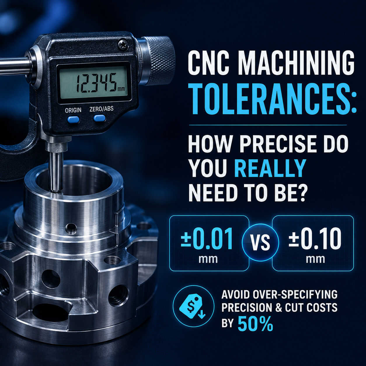
Specifying tighter tolerances than necessary is a primary cause of inflated CNC machining costs. Choosing ±0.01 mm over ±0.10 mm may feel safer, but it significantly increases machining time, inspection overhead, and scrap rates. This guide explains standard vs. precision tolerances and how to balance accuracy with manufacturing budget.
Guide 02: CNC Machining Tolerances Explained
How Precise Does Your Part Really Need to Be? | Manufacturing Academy
One of the most common mistakes in CNC part design is specifying tighter tolerances than the application actually requires. At first glance, asking for ±0.01 mm instead of ±0.10 mm may seem like a safer choice. In reality, unnecessarily tight tolerances increase machining time, inspection costs, scrap rates, and ultimately your manufacturing budget.
1. What Is a Machining Tolerance?
A tolerance defines the acceptable variation from a nominal dimension. No manufacturing method can yield exact mathematical dimensions on every part, so tolerances establish the boundary between acceptable functional parts and scrap.
For example:
· Nominal Dimension: 20.00 mm
· Specified Tolerance: ±0.05 mm
· Acceptable Size Range: 19.95 mm to 20.05 mm
The tighter the tolerance, the less variation is permitted, making the component progressively harder, slower, and more expensive to manufacture.
2. Why Tolerances Matter
In real-world CNC machining, multiple physical factors introduce slight dimensional variations during cutting:
· Tool Deflection & Wear: Cutting forces cause end mills and turning inserts to flex and wear down over time.
· Thermal Expansion: Heat generated during high-speed cutting causes raw material and machine components to expand.
· Machine Dynamics: Vibrations, backlash, and mechanical tolerances in lead screws and linear guides.
· Material Internal Stress: Raw material stock releases internal stresses when milled, leading to slight warping.
Appropriate tolerances ensure components assemble seamlessly and function reliably while allowing manufacturers to produce them efficiently without excessive scrap.
3. Common CNC Tolerance Ranges
Selecting the appropriate tolerance class prevents cost inflation. The table below outlines standard industrial CNC tolerance levels and their manufacturing implications:
Tolerance Class | Typical Value | Machining & Quality Control Impact | Cost Impact |
Coarse / Fabricated | ±0.20 mm (±0.008″) | High-speed roughing, minimal pass count, standard caliper check. | Baseline (1.0x) |
Standard Commercial | ±0.10 mm (±0.004″) | Standard CNC milling/turning speeds; standard commercial baseline. | 1.0x – 1.1x |
Fine Precision | ±0.05 mm (±0.002″) | Requires light finishing passes, controlled feeds, gauge block checks. | 1.3x – 1.5x |
Precision Fit | ±0.02 mm (±0.0008″) | Boring/fine grinding, strict thermal monitoring, micrometers / CMM. | 1.8x – 2.5x |
Ultra-Precision | ±0.01 mm (±0.0004″) | Temperature-controlled room, grinding/EDM, 100% CMM verification. | 3.0x – 5.0x+ |
💡 Engineering Insight: For over 80% of industrial mechanical components, standard block tolerances of ±0.10 mm (±0.004″) provide complete functional reliability without incurring precision pricing penalties.
4. Features Requiring Tight Tolerances vs. Non-Critical Features
Smart engineering applies high precision selectively. Differentiating functional mating surfaces from non-critical geometry is the most effective DFM cost-reduction strategy.
Feature Category | Typical Part Features | Recommended Tolerance | Design Rationale |
Critical Functional Features | Bearing seats, precision shafts, dowel pin holes, gear mounting surfaces, alignment pins, sealing grooves. | ±0.01 mm to ±0.02 mm | Directly governs alignment, press-fits, seal integrity, and mechanical motion. |
Standard Assembly Features | Mating faces, threaded hole centers, stepped shoulders, locating slots. | ±0.05 mm to ±0.10 mm | Ensures smooth assembly without requiring secondary precision operations. |
Non-Critical Features | Overall part outer dimensions, cosmetic chamfers, clearance holes, non-functional pockets, outer radii. | ±0.10 mm to ±0.20 mm | Has no impact on mechanical fit or performance; relaxes machining time. |
5. The Financial & Operational Cost of Tight Tolerances
When a drawing specifies tight tolerances across non-critical dimensions, the machine shop must adopt conservative, high-cost manufacturing protocols:
· Slower Feed Rates & Multiple Passes: Machinists must take small depth-of-cut finishing passes to avoid tool deflection, extending cycle time.
· Frequent Tool Replacement: Cutting tools must be replaced well before noticeable wear occurs to maintain strict size compliance.
· Thermal Stabilization: Parts and coolant must equalize in temperature-controlled environments prior to final pass cuts.
· Rigorous Inspection Protocols: Requires CMM (Coordinate Measuring Machine) touch probing, pin gauges, and detailed QA reports.
· Increased Scrap & Reject Rates: Minor variations that do not affect part function result in part rejection and scrapped material.
6. Design for Manufacturability (DFM) Guidelines for Tolerances
Follow these practical rules during CAD modeling to maintain high product performance at optimal manufacturing cost:
1. Use Default Title Block Tolerances: Apply general tolerances (e.g., ISO 2768-m or ±0.10 mm) to the drawing title block for non-critical geometry.
2. Leverage GD&T Over Tight Linear Dimensions: Use Geometric Dimensioning & Tolerancing (GD&T) position or perpendicularity controls rather than tightening linear coordinate dimensions.
3. Standardize Hole & Pin Sizes: Design pin holes and press-fit features around standard reamer sizes (e.g., 6 mm H7) to avoid custom tooling.
4. Establish Clear Datum References: Select logical, accessible reference surfaces as datums to simplify fixture setups and inspection measurements.
7. Collaborating with Your Manufacturing Partner
Experienced CNC suppliers review technical drawings prior to production. Engaging in a Design for Manufacturability (DFM) review allows engineers and machinists to identify overly restrictive tolerances, suggest minor CAD modifications, and optimize manufacturing cost while preserving 100% of functional requirements.
8. Conclusion & Key Takeaways
Tighter tolerances are not synonymous with better quality—they are synonymous with higher cost. Precision should be specified strictly where it directly impacts function, fit, or assembly performance.
· Default to Commercial Standards: Use ±0.10 mm (±0.004″) for standard CNC components unless function dictates otherwise.
· Target Precision Selectively: Limit tight tolerances (±0.01 – ±0.02 mm) strictly to critical mating faces, bearing seats, and alignment holes.
· Minimize Cumulative Tolerance Stack-Up: Design assemblies with clear datums to avoid stacking tight tolerances across multiple components.
· Utilize DFM Feedback: Review pre-production drawings with your machining partner to catch cost drivers early.
Next Guide: Guide 03 — CNC Milling vs. CNC Turning: Which Process Is Right for Your Part?