
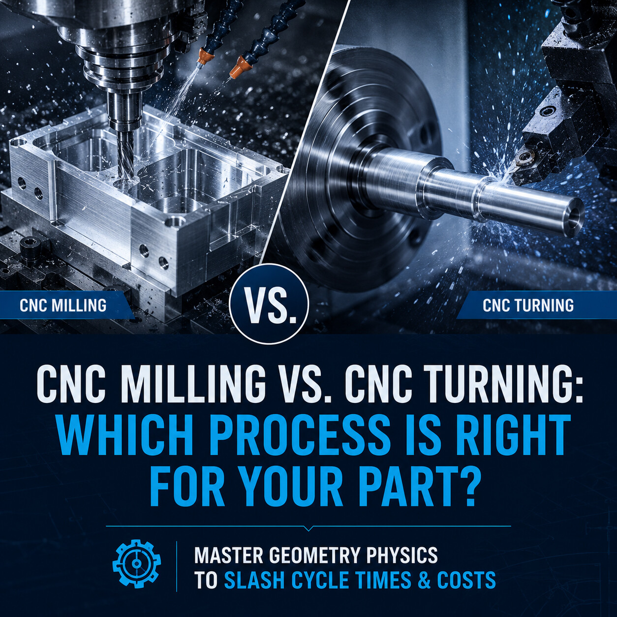
Guide 03: CNC Milling vs. CNC Turning
CNC milling and CNC turning are foundational subtractive processes in modern precision manufacturing. While both use computer numerical control to shape raw stock, they differ entirely in mechanics: milling rotates the tool against a fixed workpiece, whereas turning rotates the workpiece against a stationary tool. Selecting the correct method optimizes part quality, slashes cycle times, and lowers production costs.
Guide 03: CNC Milling vs. CNC Turning
Which Process Is Right for Your Part? | Manufacturing Academy
CNC milling and CNC turning are the two most widely used material removal processes in modern precision manufacturing. While both rely on computer numerical control to cut raw stock with high precision, they operate on fundamentally different kinematics and suit completely different part geometries. Choosing the right process at the design stage improves part quality, reduces cycle time, and significantly lowers production costs.
1. What Is CNC Milling?
In CNC milling, a rotary cutting tool (such as an end mill, face mill, or drill) rotates at high RPM while the workpiece remains stationary or moves along multiple axes (X, Y, Z, A, B, C). Milling is ideal for machining non-cylindrical, prismatic, or organic 3D shapes.
Typical milled components include:
· Electronic Enclosures: Aluminum housings with pockets, mounting standoffs, and connector cutouts.
· Mounting Brackets & Adapters: Structural parts requiring precise mounting face parallelism and hole patterns.
· Heat Sinks & Manifolds: Components with complex pin/fin arrays or internal fluid channels.
· Medical & Aerospace Structural Parts: Sculpted 3D components requiring multi-axis continuous milling.
2. What Is CNC Turning?
In CNC turning, the workpiece (typically bar stock) rotates at high speed on a precision spindle while a single-point cutting tool remains stationary or moves linearly along the X and Z axes. Turning is specifically designed for cylindrical or rotationally symmetric parts.
Typical turned components include:
· Precision Shafts & Axles: Multi-diameter cylindrical shafts with tight bearing steps.
· Bushings, Pins & Spacers: Symmetric sleeves and locating pins with high concentricity.
· Threaded Fittings & Nozzles: Components featuring precision internal or external pipe threads.
· Rollers & Flanges: Circular components requiring superior diametral runout and surface finish.
3. Key Technical Differences: Milling vs. Turning
Understanding the operational contrast between both processes ensures designs leverage machine capabilities effectively:
Technical Feature | CNC Milling | CNC Turning | Process Advantage |
Kinematics / Motion | Tool rotates at high RPM; stock moves along axes. | Workpiece rotates at high RPM; tool moves linearly. | Turning achieves superior rotational symmetry & concentricity. |
Ideal Geometry | Prismatic, flat, square, organic 3D contours. | Cylindrical, round, conical, rotationally symmetric. | Turning cuts round stock up to 3x–5x faster than milling. |
Primary Features | Pockets, slots, ribs, flat faces, complex cavities. | Outer/inner diameters, grooves, threads, tapers. | Continuous single-point cutting yields smoother turning finishes. |
Tooling Type | Multi-flute rotary cutters (end mills, drills). | Single-point insert cutting tools, boring bars. | Turning tooling is generally lower cost and faster to set up. |
Typical Equipment | Vertical / Horizontal Machining Centers (VMC/HMC). | CNC Lathes, Turning Centers, Swiss Lathes. | Swiss turning allows ultra-fast mass production of small shafts. |
4. When to Choose CNC Milling vs. CNC Turning
Select CNC Milling when your part design features:
· Flat mounting faces or datum surfaces.
· Irregular, non-symmetrical profiles or angled faces.
· Deep pockets, internal cavities, or thin internal ribs.
· Sculpted 3D organic surfaces requiring 4-axis or 5-axis toolpaths.
· Pattern of off-center drilled or tapped holes.
Select CNC Turning when your part design features:
· Rotational symmetry around a central longitudinal axis.
· Strict concentricity or runout specifications between multiple outer/inner diameters.
· Continuous internal bores or deep axial holes.
· Precision external or internal screw threads.
· Continuous circumferential grooves, chamfers, or radii.
5. Hybrid Manufacturing: Mill-Turn & Live Tooling
Many modern precision components require both turned round features and milled prismatic elements. For instance, a power transmission shaft might require precision turned bearing journals, combined with a milled keyway and cross-drilled lubrication holes.
Rather than moving parts between separate lathe and milling operations (which adds manual handling cost and introduces alignment errors), modern Mill-Turn centers integrate powered rotary tooling ('live tooling') into the lathe turret. This allows turning, off-center milling, and radial drilling to be completed in a single setup.
⚙️ Process Efficiency Tip: Designing round parts so that cross-holes and flats can be machined via live tooling on a Mill-Turn center eliminates secondary milling setups, reducing total unit cost by 25–40%.
6. Process Selection Matrix & Cost Implications
The table below summarizes optimal manufacturing processes and DFM optimization strategies for common mechanical component types:
Part Geometry / Feature | Optimal Process | Primary Cost Driver | DFM Optimization Tip |
Pure Round Shaft / Pin | CNC Turning | Machine cycle time per unit | Keep step diameters ordered to minimize tool head travel. |
Prismatic Enclosure Block | CNC Milling | Pocket clearing volume & setups | Ensure floor/wall radii match standard end mill diameters. |
Round Shaft with Keyway / Flat | Mill-Turn (Lathe + Live Tool) | Setup changes if split across machines | Align keyways and cross-holes to standard live tool angles. |
Complex 3D Contoured Surface | 5-Axis CNC Milling | CAM programming & finishing time | Avoid deep narrow cavities requiring long, fragile end mills. |
7. Conclusion & Key Takeaways
Selecting the appropriate machining process early in the engineering phase aligns design intent with optimal manufacturing physics, ensuring maximum precision at minimal cost.
· Geometry Dictates Method: Milling excels at prismatic and complex 3D shapes; Turning delivers maximum efficiency for round, symmetric components.
· Turning Is Faster for Round Stock: Continuous cutting speeds in turning yield lower unit costs for shafts, pins, and bushings.
· Leverage Mill-Turn Capabilities: Consolidate turned and milled features into single-setup Mill-Turn operations to eliminate handling errors.
· Design to Match Machine Kinematics: Align part features with standard cutting tools to minimize custom setup requirements.
Next Guide in Series: Guide 04: 3-Axis vs. 5-Axis CNC Machining: Do You Really Need 5 Axes?