
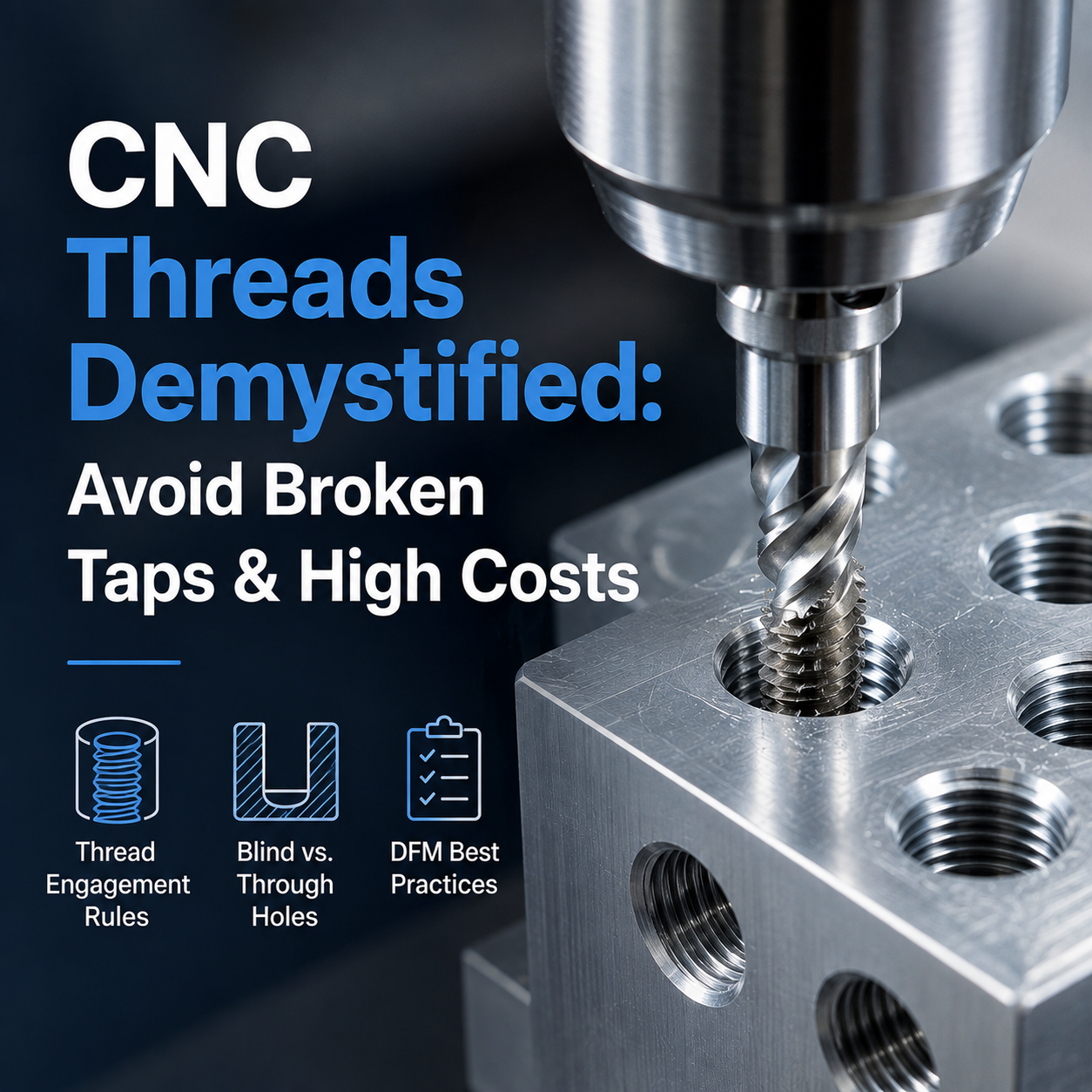
Guide 08: CNC Threads Explained: Everything You Need to Know Before Designing Threaded Holes
Threaded features are critical yet frequently mismanaged in CNC design. Poor hole depth, non-standard sizing, or improper placement inflate machining times, complicate inspection, and cause assembly failures. Mastering thread design standards prevents costly production bottlenecks.
Guide 08: CNC Threads Explained: Everything You Need to Know Before Designing Threaded Holes
Thread Standards, Depth Recommendations, Hole Types & DFM Guidelines | Manufacturing Academy
Threaded holes are among the most common features in machined parts. Whether you're designing a consumer electronic enclosure, an industrial fixture, or an aerospace component, chances are your part will include tapped holes for screws, bolts, or inserts. Yet threaded holes are also one of the most frequently misunderstood features in CNC machining. Overly deep threads, non-standard specifications, or poor placement can increase machining time, complicate inspection, and even lead to assembly issues.
1. What Is a Threaded Hole?
A threaded hole features internal helical threads that allow a threaded fastener to screw directly into the part, providing robust mechanical engagement without requiring a separate nut. Tapped holes are essential for mechanical assemblies, robotics, medical devices, automotive housings, and industrial automation.
2. Common Thread Standards
Metric Threads (ISO): Default international standard. Examples: M3×0.5, M4×0.7, M5×0.8, M6×1.0, M8×1.25.
Unified Threads (UNC/UNF): Standard in North America. Examples: #4-40, #6-32, 1/4-20 UNC, 3/8-16 UNC.
Pipe Threads (NPT / BSPP): Designed specifically for fluid and gas sealing connections.
3. How CNC Machines Create Threads
Cut Tapping: A tap cuts threads into a pre-drilled hole. Fast, economical, and suitable for most general applications.
Thread Milling: A rotating thread mill follows a circular helical path. Ideal for large thread diameters, tough materials (Stainless Steel, Titanium), and precise pitch control.
Form Tapping (Thread Rolling): Plastically deforms ductile materials (Aluminum, Brass, Copper) without generating chips, producing exceptionally strong threads.
4. Recommended Thread Depth Guidelines
A common misconception is that deeper threads always yield stronger joints. In reality, thread engagement beyond 1.5–2.0 times the nominal diameter provides negligible additional holding strength while significantly increasing tap breakage risks and cycle times.
Substrate Material | Recommended Engagement Depth | Example (M6 Fastener) |
Steel & Hard Alloys | 1.0 × Nominal Diameter | 6.0 mm Effective Thread Depth |
Aluminum Alloys | 1.5 × Nominal Diameter | 9.0 mm Effective Thread Depth |
Engineering Plastics | 2.0 × Nominal Diameter | 12.0 mm Effective Thread Depth |
5. Blind Holes vs. Through Holes
Blind Holes: Holes that do not pass completely through the part. Excellent for liquid sealing and cosmetic exteriors, but require extra drill depth and bottom clearance for tap chips.
Through Holes: Holes extending entirely through the workpiece. Preferred for manufacturing because they allow easier chip evacuation, faster tapping speeds, and lower tooling risk.
6. Critical Thread Relief & Clearance
Taps cannot cut full-depth threads all the way to the conical tip of a blind hole. Always design a thread relief depth—leaving unthreaded clearance below the active thread engagement zone to accommodate drill point angles and tap chamfers.
💡 DFM Rule for Threaded Holes: Always prefer through holes over blind holes when cosmetic or sealing constraints allow. For blind holes, ensure unthreaded clearance at the bottom equals at least 0.5× the hole diameter.
7. Common Thread Design Mistakes
Specifying Non-Standard Thread Sizes: Increases custom tap costs and inspection delays.
Placing Threads Too Close to Edges: Risks sidewall bulging or cracking during tapping.
Using Tiny Threads Unnecessarily: Micro-threads (< M2) fragile tools susceptible to breakage.
8. Thread Callout Best Practices
Clear engineering drawings prevent production ambiguity. Specify: Thread Designation, Thread Depth, Hole Depth (for blind holes), Quantity, and Class of Fit.
Drawing Callout Example: Example Callout: 8× M6×1.0 - 10 mm Thread Depth / 13 mm Hole Depth
Conclusion & Key Takeaways
Optimal Depth: Keep thread engagement within 1.0x–2.0x diameter limits to prevent tap breakage.
Through Hole Preference: Specify through holes wherever possible for superior chip clearing.
Standardization: Standardize thread pitches and sizes across assemblies to reduce setup time.